Electronics – Final Chapter.
Welcome back to the final instalment of the Sand Scorcher restoration!
We last left off mechanical re-assembly. Now, we will finish off the electronics:
Since this car will not be ran a lot due to age and the motor being stock, I figured we would go “mild” with the required components. For the controller, I have had a lot of good results with the Spektrum in my 2011 Scorcher and choose the STX3 controller and receiver combo:
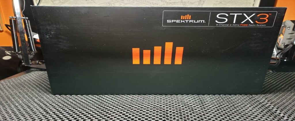
This STX3 is a nice entry level controller from Spektrum. However, even though it lacks a digital readout, it works well and has the trim adjusters that are necessary.
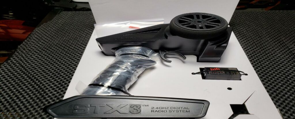
The receiver is quite small and lightweight. My only complaint is the antenna wire is a little shorter than I would like.
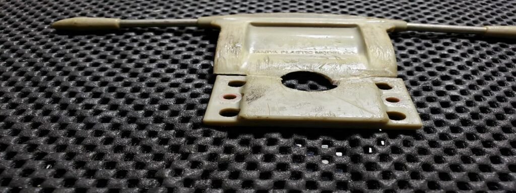
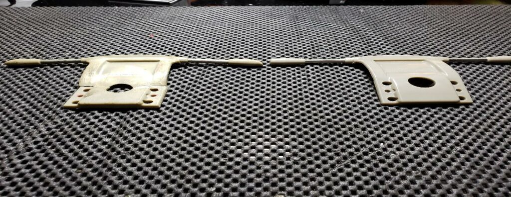
My 2011 came with an ESC (Electronic Speed Controller). The 1979 came originally with a clunky mechanical speed controller. These were servo operated and tended to arc. They were not the most accurate. I decided to purchase the same style Tamiya controller as in my 2011.
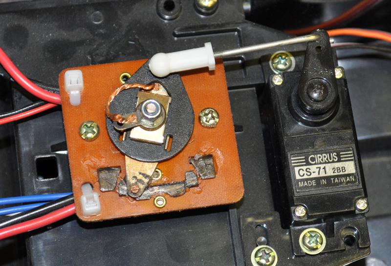
Not exact, but a typical style found back in the day.
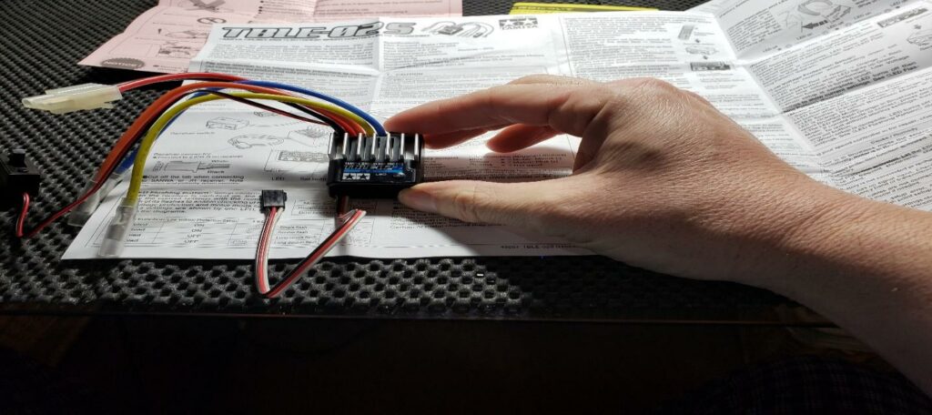
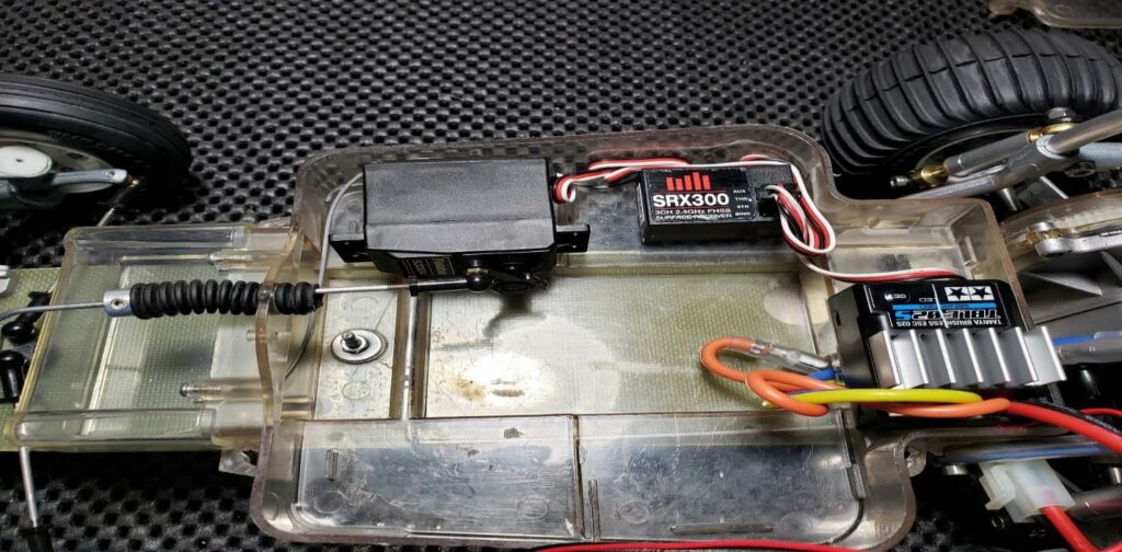
This is a much cleaner setup!
STEERING SERVO
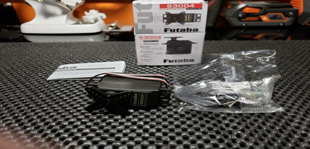
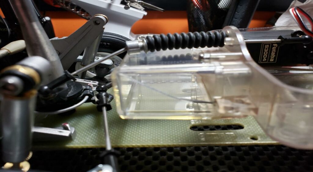
For steering, I decided on using a Futaba S3004. These are a reliable unit, and this is a smaller, higher torque version.
TEST FITTING THE COMPONETS
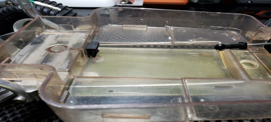
The radio box may look a little scratched up. Remember, this is an original first issue. We did not want to go with a ‘perfect restoration’ with this unit.
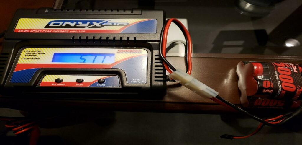
I set up all of the components loosely in the car and charged a 5 cell hump-pack style battery. This style of battery works best with the Sand Scorcher radio box.
Using the trim adjusters on the controller I was able to dial in the steering and throttle trim, so we have peak acceleration and optimal steering in both directions:
It is best to put the receiver antenna wiring as far from the ESC as possible to avoid interference. So, we will run it into the front of the radio box. We will also check the steering rod from the steering servo to the steering servo saver and adjust the length as required:
All the components checked out OK by following this link:
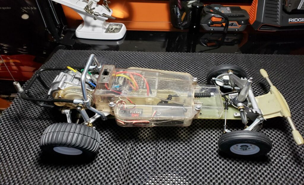
Now, using double sided tape, we will find the best position for the components:
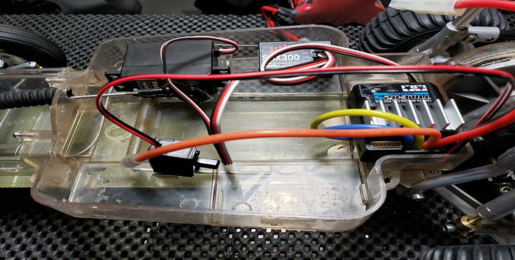
Now, we will clean-up the wiring. That is better!
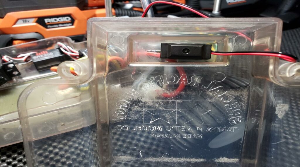
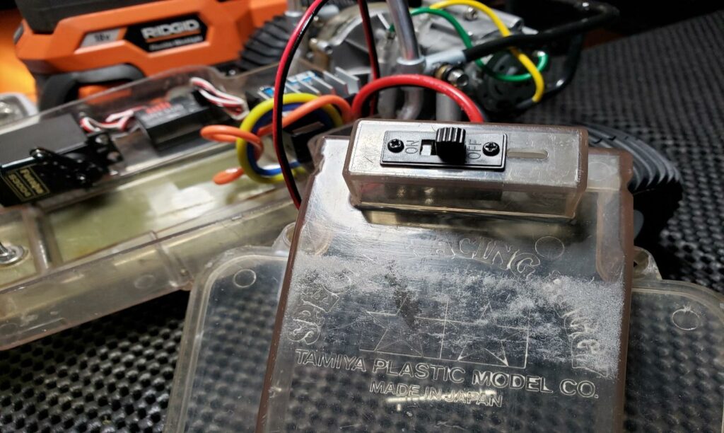
Next, we will install the ESC power switch in the top of the radio box:
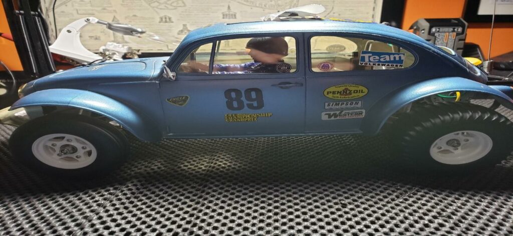
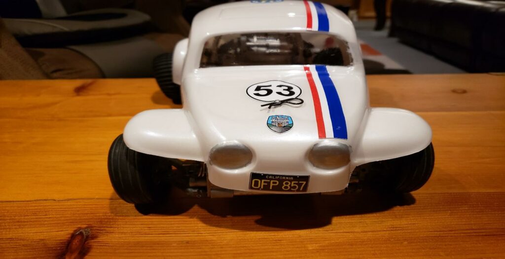
This is one of my favourite photos. It has been a long time since the car has looked this good! The antenna wiring is supposed to wrap around the antenna, but as I mentioned earlier, it is a bit short. In the days of the old AM frequency radios, this would be a concern, but running 2.5 GHZ, but not now.
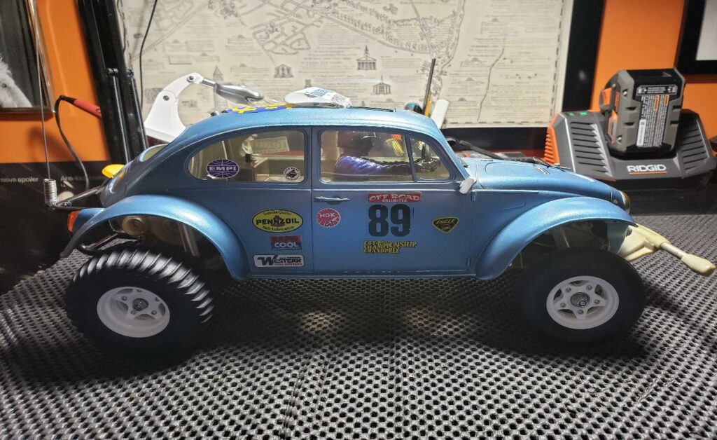
Okay, I like these pictures even better!
Now, a bit of a confession. The car ran great, but remember that computer crash? We lost the video from this day. Second, I was always concerned about the rigidity of that original bumper. On this run, a weak section in the plastic finally let go and the bumper came apart. As of Feb 9, I have found a NOS grey bumper for this car!
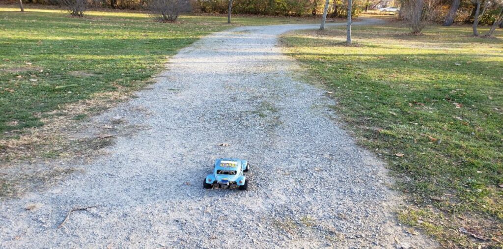
Finally, with the new bumper attached and the weather cleared up, the Scorcher was able to make a second run!
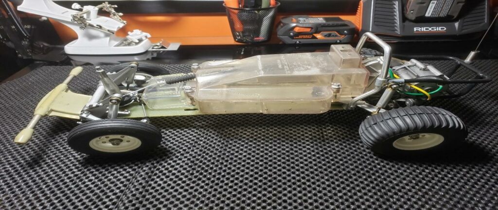
Remember the old leftover parts? While waiting for the bumper & working on the computer situation, I did this little sideline project:
Not perfect, but it is a “rolling chassis” with some eBay parts deals.
I would like to thank everyone for taking the time to check out the article and patiently awaiting each new segment. I am working on some other projects, and will hopefully be doing some much shorter articles in the future.
If you have questions or comments, feel free to contact me at: